Application-Tested Handling
Product transfer and pack formation are confirmed around representative samples.
Turnkey Packaging Lines
A coordinated compact line combining conveying, inspection, packing and end-of-line handling under one technical scope and project-delivery process.
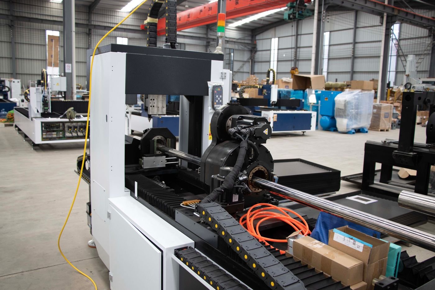
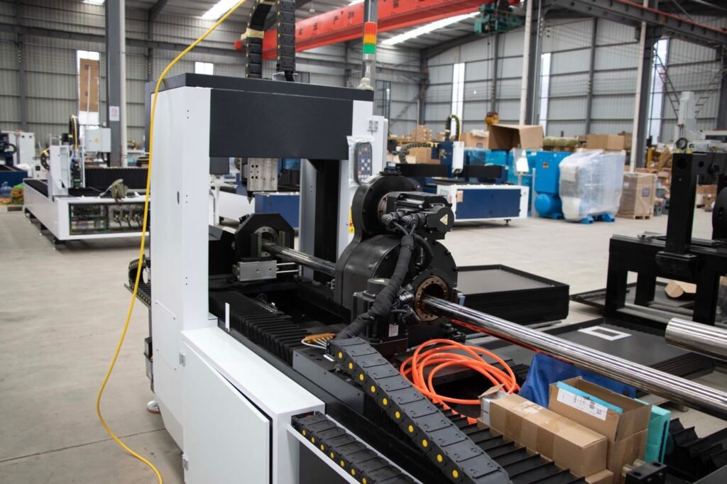
Line CL-200
A coordinated compact line combining conveying, inspection, packing and end-of-line handling under one technical scope and project-delivery process.
Product transfer and pack formation are confirmed around representative samples.
Stored settings and guided adjustments support multiple product formats.
Signals, transfer heights and accumulation logic are defined with adjacent equipment.
Electrical standards, documentation and commissioning scope can be adapted by market.
Equipment Snapshot
Demonstration figures show how a professional equipment page can present the operating range without hiding project-dependent conditions.
Equipment count and boundary are project specific.
Interface philosophy defined before build.
Run agreed products through the coordinated line.
Remote and on-site scope available.
Equipment Overview
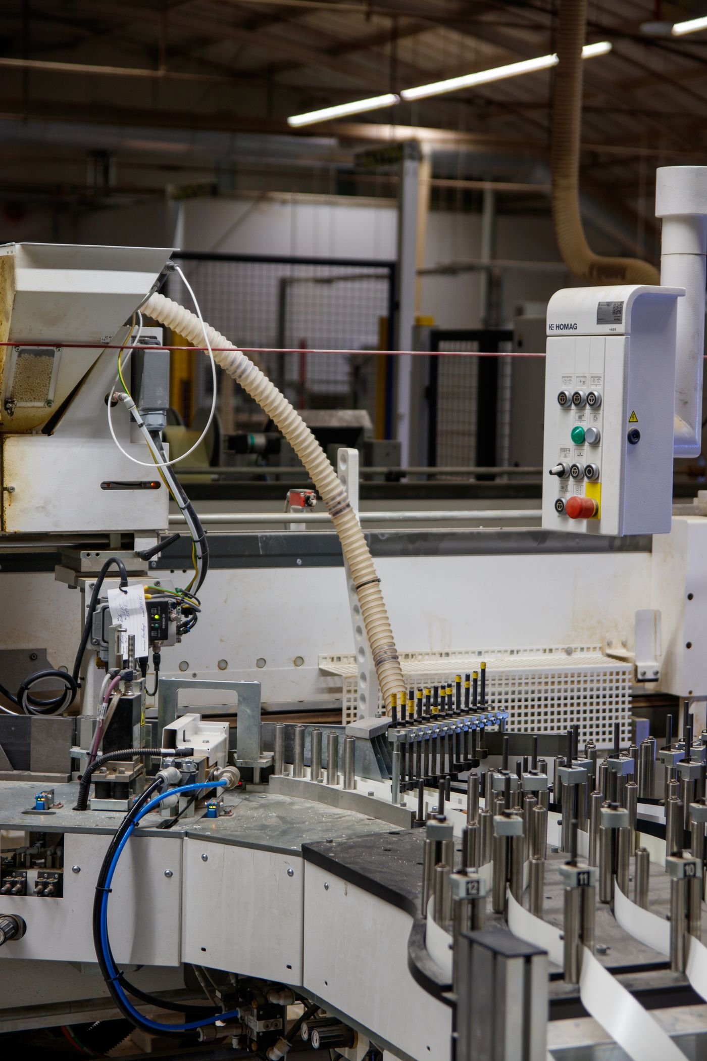
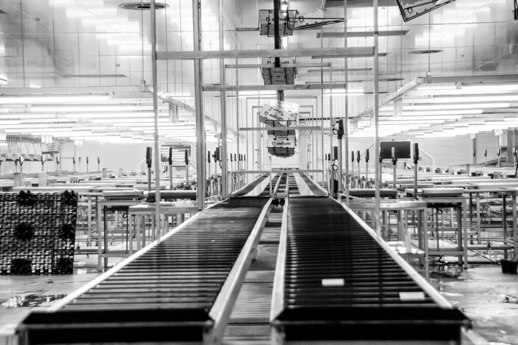
The CL-200 is an application-engineered line concept rather than one fixed machine. Equipment is selected around product flow, packaging sequence, target output, labor goals, utilities and the existing factory layout.
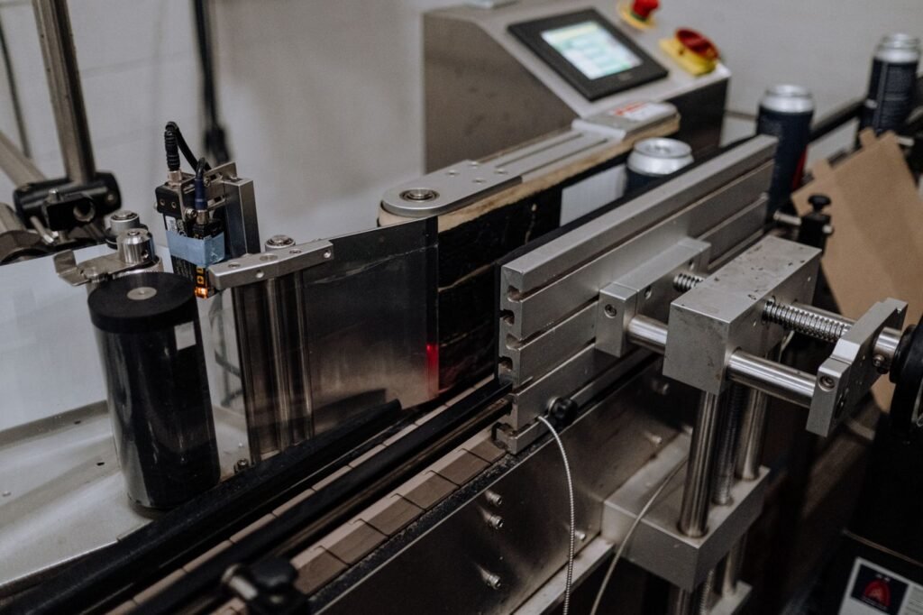
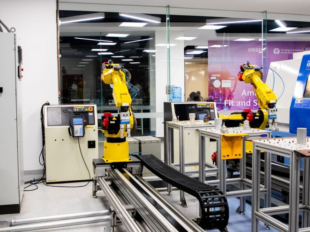
The line scope can combine product handling, labeling or inspection, secondary packaging, conveying and robotic palletizing. A central controls layer coordinates run permission, fault status, recipes and production visibility across the selected machines.
Project boundaries, interfaces, acceptance criteria and site responsibilities are documented before manufacturing. This allows the buyer to compare a complete system scope rather than several disconnected equipment quotations.
Technical Specifications
Final values are confirmed after sample, layout, utility and interface review. Each row can include an explanatory note instead of presenting isolated numbers.
Bottleneck study uses every machine and transfer.
Final selection follows process requirements.
Central or distributed control options available.
Ownership and parameter synchronization are defined.
Risk assessment covers machine and line boundaries.
Connection points are listed by equipment.
Includes approved layout and responsibility matrix.
Milestones are linked to technical approvals.
Project Advantages
These benefits come from application review, defined interfaces and measurable acceptance criteria rather than decorative feature claims.
Equipment selection, interfaces and line behavior are reviewed as one system.
Responsibility for utilities, conveyors, guarding, data and site work is documented.
Products pass through the coordinated process instead of testing each machine in isolation.
Installation sequence, training, spare parts and remote support are prepared before shipment.
Typical Applications
Application suitability is confirmed against real samples, speed and environmental conditions before the final machine configuration is released.
Complete packaging and end-of-line systems for a new facility or product.
Replace manual operations or isolated machines while retaining useful equipment.
Add parallel equipment, buffering or end-of-line automation to remove bottlenecks.
Coordinate recipes and changeover across several machines.
Configuration & Integration
A complete quotation identifies what the machine receives, what it delivers and which functions belong to adjacent equipment or the customer site.
Transfer height, product orientation, access, guarding and installation clearances.
Power, safety, run permission, fault status, speed references and network connections.
Samples, utilities, local work, lifting, installation, validation and site acceptance responsibilities.
Operating Sequence
The project is controlled through technical approvals and measurable acceptance gates.
Map products, packaging steps, target output, labor and current constraints.
Select equipment, develop flow and define supplier and customer responsibilities.
Approve layout, interfaces, controls, guarding, utilities and FAT criteria.
Build machines, controls and software under a coordinated project schedule.
Test the process, close actions, commission on site and train the operating team.
Configuration Comparison
Use the same comparison factors when evaluating competing technical proposals.
| Project Factor | Standalone Machine | Integrated Cell | Turnkey Line |
|---|---|---|---|
| Best for | One defined operation | Several coordinated processes | Complete production flow |
| Interfaces | Local infeed and discharge | Cell-level machine handshakes | Line-wide controls and responsibilities |
| Acceptance | Machine FAT | Coordinated cell FAT | Integrated process FAT |
| Site planning | Utility and access check | Cell installation plan | Phased installation and ramp-up plan |
| Project management | Equipment schedule | Multi-discipline coordination | Full technical milestone control |
Technical Review
Each tab answers a different procurement question and demonstrates a deeper product-content structure.
Cycle times, buffers, quality checks, manual work and product transitions are reviewed before equipment is selected.
Columns, aisles, utilities, operator routes, maintenance zones and future expansion are included in scaled layout reviews.
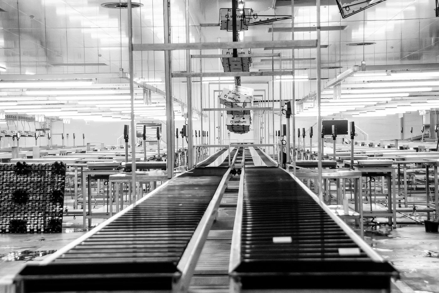
Recipe ownership, line states, fault handling, data exchange and restart philosophy are approved before programming begins.
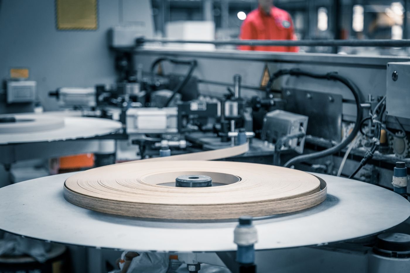
Representative products move through the complete available scope while output, quality, alarms, safety and recovery are recorded.
Site readiness, unloading, positioning, utilities, contractor work, training and production support are assigned to a dated plan.
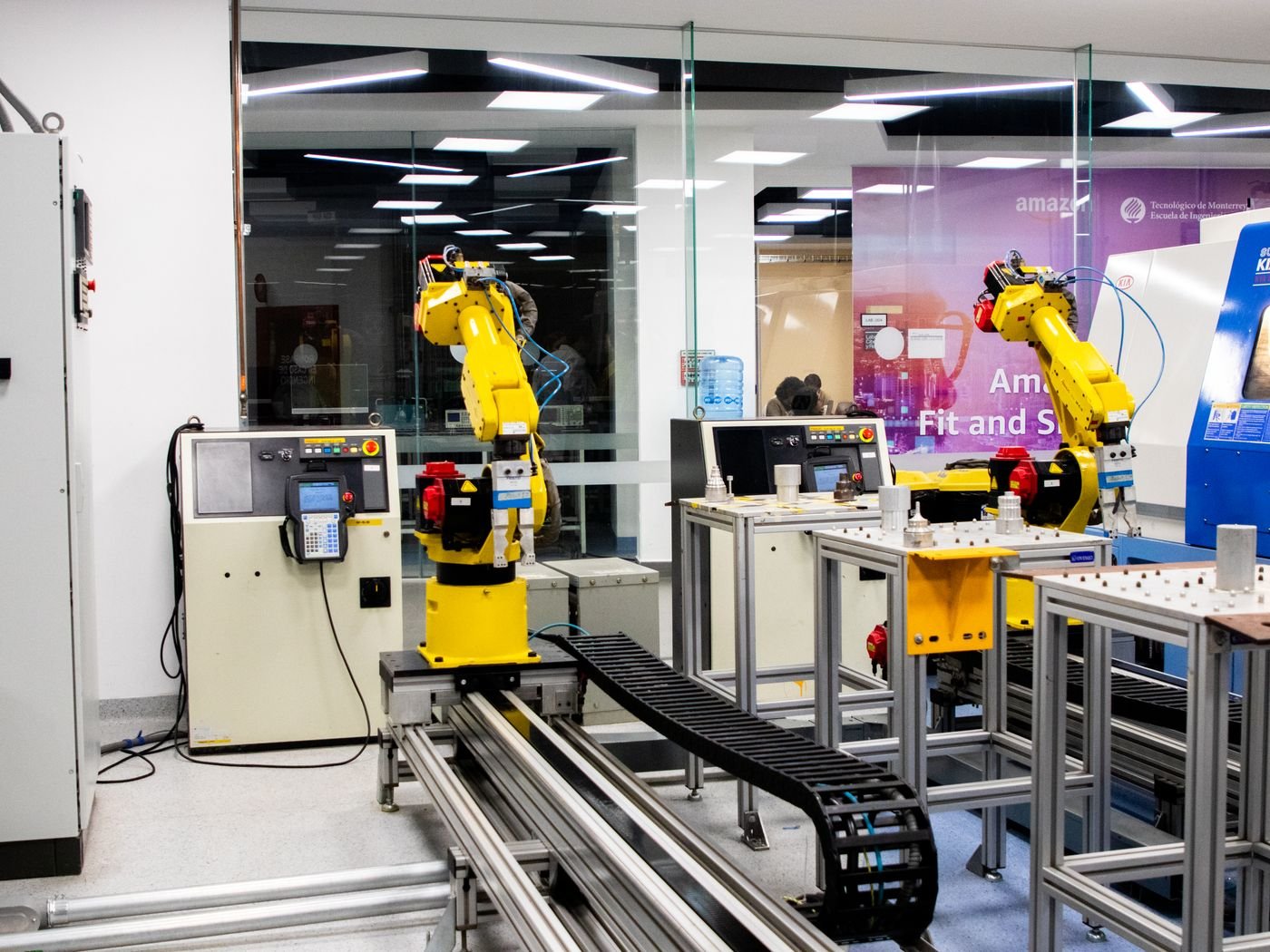
Factory Acceptance Testing
Testing uses agreed samples, functions and acceptance methods. Project-dependent items are recorded rather than hidden.
Confirm process, layout, interfaces, components and acceptance criteria.
Complete mechanical, electrical and software checks for each equipment module.
Run representative products through the available complete process.
Challenge line stops, blocked conditions, reject events and controlled restart.
Review drawings, software backups, manuals, training and outstanding actions.
Procurement Risk Review
A professional product page should make risk and project assumptions visible, not only list attractive features.
Rated speed is quoted without product and operating assumptions.
Tie output to approved samples, format, buffer condition, reject logic and FAT method.
Machine boundaries and adjacent-equipment responsibilities are unclear.
Approve a layout, interface list and responsibility matrix before manufacturing.
Installation and ramp-up support are discussed after shipment.
Define site readiness, commissioning, training, spares and remote support in the project scope.
Project Documents
These demonstration resources show how an independent site can present technical depth and reduce uncertainty before inquiry.
Equipment FAQ
The answers identify what must be confirmed during technical review instead of presenting unsupported guarantees.
Provide product and packaging details, current process, target output, floor plan, utilities, labor goals, destination standards and any equipment that must remain in the line.
A responsibility matrix identifies equipment, utilities, site work, network, lifting, installation, samples, local contractors and acceptance activities.
Yes, after reviewing drawings, operating condition, controls, transfer heights, signals and available access. Interface risk is documented before the final concept.
Output is tied to agreed products, formats, operating assumptions, buffer conditions and an FAT method. The proposal identifies any limiting process.
Installation supervision, commissioning and training can be included. The scope depends on destination, local contractor capability and site readiness.
Spare I/O, mechanical space, recipe architecture and expansion interfaces can be planned when future requirements are known during concept design.
Related Equipment
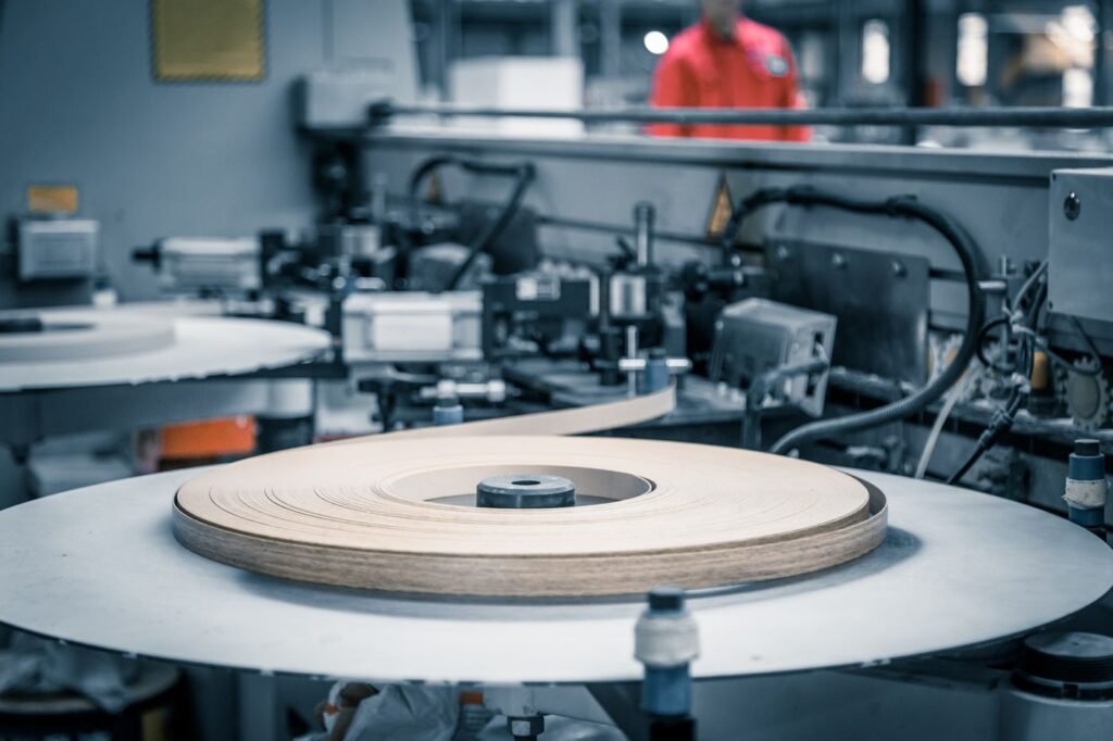
Review upstream, downstream and complementary equipment using the same structured product system.
Buyer Resources
Long-form selection guides help buyers prepare better inputs, evaluate suppliers and define acceptance criteria.
Request a Technical Proposal
Attach representative product photos, drawings, packaging information or a short production video. The first response should identify missing technical inputs and a practical next step.